Why Choose Pneumatic Valves for Industrial Applications?
Pneumatic Valves remain a practical choice for factories that need fast, repeatable motion and dependable process control. They direct compressed air to cylinders, actuators, and other devices with remarkable simplicity. In a packaging line, a valve can extend a pusher, release a clamp, or stop a product within seconds. Their compact design also fits crowded machinery frames. This matters where electrical space is limited or frequent washing creates harsh operating conditions.
Pneumatic systems are often valued for their safety in potentially wet or combustible areas. They produce no electrical sparks at the point of actuation. Properly selected components can also withstand vibration, temperature changes, and demanding production cycles. Standards such as ISO 4414 support safer pneumatic system design, although compliance requires careful engineering rather than a label alone. Air quality is critical. Water, oil, and particles can damage seals and cause sluggish movement. Regular filtration, pressure checks, and leak inspections improve reliability and reduce wasted energy.
Still, Pneumatic Valves are not a perfect answer. Compressed air generation can be expensive, especially when leaks remain unnoticed above a noisy production floor. Electric or hydraulic alternatives may suit applications requiring precise positioning or very high force. The right decision depends on cycle speed, load, environment, maintenance skill, and total operating cost. Real plants are rarely textbook-clean. That is why experienced engineers test valve response, review manufacturer data, and observe performance under actual working conditions before approving a final design.
What Are Pneumatic Valves and How Do They Work?
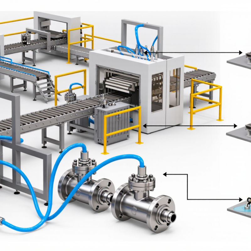
Pneumatic valves are control devices that manage compressed air in industrial systems. They direct airflow toward cylinders, grippers, or other pneumatic actuators. A valve can start, stop, throttle, or redirect air. Think of it as a traffic controller for pressurized air. It does not create pressure. The compressor and air preparation equipment do that work.
Inside the valve, a spool, poppet, or diaphragm changes position. When an electrical signal reaches a solenoid, the mechanism moves and opens selected passages. Compressed air then enters one actuator port, while used air exits through another. Reversing the signal can retract a cylinder or release a gripper. Spring-return valves move back when the signal stops. Directional markings, such as 3/2 or 5/2, show the number of ports and operating positions.
This simple action explains why many factories choose pneumatic valves. They can switch quickly, tolerate frequent cycling, and operate safely near heat or moisture when properly specified. However, they are not maintenance-free. Water in compressed air can corrode parts and cause sluggish movement. Poor sizing can create pressure loss, noise, or incomplete strokes. In practice, technicians check air quality, flow requirements, response time, and actuator load before installation. I have found that small leaks are easy to ignore at first. That is a mistake. A routine inspection often reveals worn seals, loose fittings, or exhaust restrictions before production suffers.
| Data Dimension | Key Information | Industrial Relevance |
|---|---|---|
| Definition | A pneumatic valve is a mechanical device that controls the direction, pressure, or flow of compressed air or other gases. | It provides controlled pneumatic power for actuators, cylinders, grippers, and automated machinery. |
| Operating Principle | The valve changes the connection between inlet, outlet, and exhaust ports when its internal spool, poppet, or diaphragm moves. | This movement determines whether an actuator extends, retracts, stops, or remains in a defined safety position. |
| Typical Control Methods | Common actuation methods include solenoid control, manual operation, mechanical actuation, pilot air, and pneumatic control signals. | The control method can be selected according to automation level, available energy, response requirements, and operating environment. |
| Common Valve Functions | Directional control valves route air; pressure-control valves regulate pressure; flow-control valves adjust airflow; shut-off valves isolate circuits. | Using the correct function helps control motion, protect components, and improve process repeatability. |
| Port and Position Designation | Directional valves are commonly identified by the number of ports and switching positions, such as 2/2, 3/2, 4/2, and 5/2 configurations. | A 3/2 valve is often used with single-acting actuators, while a 5/2 valve is commonly used with double-acting cylinders. |
| Energy Source | Pneumatic valves operate with compressed air supplied by an air compressor and distributed through a prepared air system. | Reliable performance depends on suitable pressure, adequate flow capacity, filtration, and effective condensate management. |
| Response Speed | Pneumatic systems can provide rapid switching and actuator movement because air signals and lightweight valve components can respond quickly. | Actual cycle time depends on valve flow capacity, tubing length, actuator size, air pressure, load, and exhaust restrictions. |
| Force and Motion Control | Actuator force is primarily influenced by air pressure and piston area, while movement speed is strongly affected by airflow and flow-control settings. | This makes pneumatic valves suitable for repetitive clamping, pressing, sorting, conveying, and pick-and-place operations. |
| Safety Characteristics | Pneumatic systems can be designed to exhaust air, hold a position, or return an actuator to a predetermined state when control power is removed. | Fail-safe behavior must be engineered for the specific machine, load, actuator, and risk assessment; it is not automatic for every valve. |
| Electrical and Fire Considerations | The working medium is compressed air rather than hydraulic oil, and pneumatic valves can be configured for low electrical power or remote pneumatic control. | This can be advantageous where clean operation, reduced fluid-spill risk, or specific electrical-area requirements are important. Area certification must be verified separately. |
| Cleanliness | Compressed air does not leave hydraulic-oil residue at the actuator, although the air supply may contain water, oil aerosols, or particles if it is not treated. | Filtration, drying, lubrication where required, and correct material selection are essential for food, pharmaceutical, electronics, and clean manufacturing environments. |
| Maintenance Requirements | Routine care typically includes checking for air leaks, maintaining filters and dryers, inspecting tubing and fittings, and verifying valve response. | Leak prevention reduces compressor workload, operating cost, noise, and loss of available actuator performance. |
| Installation Flexibility | Valves are available as individual units, manifold-mounted assemblies, or integrated valve terminals with centralized connections. | Modular designs simplify machine layout, troubleshooting, expansion, and connection to industrial control systems. |
| Environmental Limits | Performance may be affected by temperature, moisture, contamination, corrosive atmospheres, vibration, and unsuitable compressed-air quality. | Valve seals, body materials, enclosures, and protection ratings should be selected for the actual installation conditions. |
| Typical Applications | Pneumatic valves are widely used in packaging, assembly, material handling, process automation, machine tools, printing, and general manufacturing. | They are especially effective for repetitive on/off motion and applications requiring simple, robust, and relatively lightweight actuation. |
| Main Advantages | Fast switching, compact construction, simple control, clean working medium, easy modular integration, and reliable repetitive operation. | These advantages support efficient automation when the required force, precision, speed, and air infrastructure are properly matched. |
| Important Limitations | Compressed-air generation can be energy-intensive, air is compressible, precise positioning may require additional control technology, and leaks reduce efficiency. | For high-force, high-efficiency, or highly precise motion, hydraulic or electric alternatives may be more appropriate depending on the application. |
| Selection Criteria | Select the valve according to function, number of ports and positions, operating pressure, required flow, response time, connection size, seal compatibility, temperature range, and control signal. | Correct sizing prevents inadequate actuator speed, excessive pressure drop, unnecessary energy use, and premature component wear. |