Why Choose Ceramic Laser Reflectors for Industrial Lasers?
Why Choose Ceramic Laser Reflectors for Industrial Lasers?
Industrial lasers are becoming more powerful, compact, and thermally demanding. That shift makes reflector materials a critical engineering decision, not a minor component choice. Fortune Business Insights valued the global laser technology market at approximately USD 18.1 billion in 2023. Its report also forecasts continued growth through 2032. Behind that expansion are demanding applications, including cutting, welding, marking, medical systems, and semiconductor processing.
Ceramic Laser Reflectors help manage these challenges through high reflectivity, thermal stability, and resistance to repeated heating cycles. Their polished surfaces can redirect laser energy efficiently inside resonators and pump chambers. Their low thermal expansion helps reduce alignment drift when operating temperatures change. In practical terms, the reflector must survive thousands of cycles without developing hotspots, cracks, or coating failure. Small defects can become expensive downtime.
Dr. Akio Ikesue, a pioneer in transparent laser ceramics, stated, “The performance of ceramic materials depends strongly on controlling their microstructure.” That observation remains relevant for industrial reflectors. Manufacturing quality affects porosity, surface finish, mechanical strength, and optical consistency. Reports from MarketsandMarkets also identify laser optics as a growing segment, driven by automation and higher-power systems. However, market growth does not guarantee reliable performance. Material selection still requires testing under real operating conditions. Engineers should examine wavelength, cooling design, coating compatibility, and reflector geometry before purchasing. Ceramic reflectors are not automatically superior. Their value depends on correct design, careful processing, and honest performance data.
Ceramic Laser Reflectors: Definition and Core Function
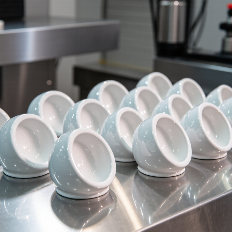
Ceramic laser reflectors are engineered optical components that redirect laser energy inside an industrial laser system. Their core function is simple: guide useful light back toward the active medium or target path. A dense ceramic body supports a reflective surface, often shaped to match the lamp, laser rod, or optical cavity. This geometry helps reduce energy loss and improve beam utilization.
In practical systems, ceramic reflectors handle heat, repeated cycling, and strong radiation better than many ordinary materials. Their low thermal expansion helps maintain alignment when equipment changes temperature. This matters during long cutting, welding, or marking cycles. A small surface defect can still scatter light and lower efficiency. I have seen maintenance teams overlook this point. Reflectivity alone does not guarantee stable performance. The wavelength, surface finish, cavity shape, and cooling design must work together.
Tips: Check the reflector under controlled lighting before installation. Look for chips, cloudy areas, contamination, or uneven coating. Confirm its wavelength range and temperature rating. Keep cleaning gentle; aggressive tools may create microscopic scratches. Record operating hours and inspect performance changes. Replacement timing is not always obvious, so trend data can reveal gradual losses before they affect production.
How Ceramic Laser Reflectors Work in Industrial Systems
Ceramic laser reflectors help industrial laser systems use pump energy more efficiently.
In many solid-state lasers, a lamp or diode array produces light around the gain medium. The reflector surrounds this region and redirects useful light toward the laser rod or active crystal. Its curved surface controls the light path. Some designs use polished ceramic, while others use a reflective coating over a heat-resistant body.
During operation, the reflector faces intense radiation, rapid temperature changes, and repeated cleaning cycles. Technical ceramics remain stable under these conditions and resist deformation better than many ordinary materials.
Their thermal performance also helps maintain cavity geometry. Even a small shift can reduce coupling efficiency or create uneven heating. Alignment matters greatly.
The result is more consistent energy transfer.
In practice, engineers inspect surface finish, reflector shape, mounting pressure, and cooling airflow. Dust can scatter light. Tiny cracks may grow during thermal cycling.
A calculation may predict excellent performance, yet real production conditions can disagree. That is why experienced teams verify reflectors through power measurements, thermal imaging, and long-duration testing.
Ceramic is not automatically perfect. Its performance depends on material quality, dimensional accuracy, coating condition, and the surrounding laser design. A reflector that works well in one cavity may perform poorly in another. Careful validation remains necessary.
Key Advantages Over Glass and Metal Reflectors
Why Choose Ceramic Laser Reflectors for Industrial Lasers?
Ceramic laser reflectors manage heat more reliably than many glass and metal alternatives. ASM Handbook data places alumina’s thermal expansion near 7–8 × 10⁻⁶/K. Copper is about 17 × 10⁻⁶/K, while fused silica is near 0.5 × 10⁻⁶/K. This middle range can reduce alignment drift during repeated power cycles. Ceramic surfaces also resist oxidation and softening at elevated temperatures. That matters inside cutting heads, beam delivery units, and high-duty-cycle welding systems. Glass can crack after uneven heating. Metal can absorb more energy, deform, or develop surface oxidation.
The advantage is not automatic. Coating quality, surface roughness, wavelength, and cooling design still control performance. NIST thermophysical-property data shows that thermal conductivity varies greatly between ceramic compositions. A dense alumina reflector may behave very differently from a porous ceramic part. Engineers should request measured reflectance at the operating wavelength, not a generic percentage. A small surface defect can scatter the beam and create a bright thermal spot. It happens.
Tips: Check reflectance after thermal cycling, not only before installation. Confirm the ceramic grade, pore structure, mounting stress, and coolant path. Leave room for inspection. Ceramic can survive heat, but it may chip from careless handling or uneven clamping. That practical weakness deserves more attention in procurement decisions.
Why Choose Ceramic Laser Reflectors for Industrial Lasers?
Representative thermal-property comparison of alumina ceramic, fused silica glass, copper, and aluminum reflector substrates. Alumina offers higher thermal conductivity than fused silica and a lower coefficient of thermal expansion than common metals, helping reduce thermally induced distortion in demanding laser systems.
Values are representative room-temperature properties and vary with grade, purity, porosity, and manufacturing process. Thermal conductivity is shown in W/m·K; coefficient of thermal expansion is shown in µm/m·K. Reflector performance also depends on surface finish and optical coating design.
Industrial Applications and Performance Requirements
Ceramic laser reflectors support demanding industrial laser systems, especially solid-state cavities used for cutting, welding, drilling, and precision marking. Their ceramic bodies tolerate repeated heating, cooling, and vibration better than many conventional reflective materials. In a busy production line, this matters when a laser operates for long shifts beside coolant channels and moving stages.
Performance starts with the laser wavelength. A reflector must provide high reflectivity with minimal absorption at the operating band. Even small absorption can create hot spots, shift alignment, and reduce output stability. Thermal shock resistance is equally important. A reflector may face rapid temperature changes during startup, pulsed operation, or emergency shutdown. Engineers should also check dimensional tolerances, surface finish, porosity, and compatibility with the cavity’s cooling environment.
Industrial users often inspect reflector geometry after installation, not only during incoming quality checks. Dust, coolant residue, and fingerprints can reduce optical performance. Cleaning procedures should follow approved material data and avoid abrasive contact. A practical specification should include reflectance testing, thermal cycling data, and inspection limits for chips or cracks. A perfect reflector is an engineering idea, not a shop-floor reality. Small defects may be acceptable in one cavity but harmful in another. That judgment requires measured test results, stable process control, and honest review of operating conditions.
Selection, Installation, and Maintenance Considerations
Selecting a ceramic laser reflector starts with the laser’s wavelength, power density, and beam geometry. Reflectivity alone is not enough. The reflector must tolerate thermal gradients, repeated pulses, and the planned incidence angle. Check the ceramic substrate, surface finish, aperture, and coating specification against the equipment manual. For high-power systems, confirm damage threshold data under comparable pulse duration, spot size, and cooling conditions. A reflector rated for average power may fail under short, intense pulses. I have seen that mismatch create tiny pits before operators noticed output loss.
Installation demands a clean, controlled workspace. Isolate the laser and follow documented lockout procedures before opening the optical path. Wear powder-free gloves, hold the part by its edge, and keep dust away from the reflective face. Use the specified mount, torque, and orientation; excessive clamping can stress the ceramic. Align with a low-power, approved procedure before applying full operating power. Never correct alignment by forcing the holder. That shortcut is tempting. Verify beam centering, clearance, and cooling airflow after installation, then record baseline power and spot quality.
Maintenance should follow measured condition, not habit alone. Inspect the surface through suitable laser-safe viewing methods, checking for haze, deposits, chips, or coating discoloration. Clean only when contamination affects performance or inspection. Use the approved solvent, lint-free materials, and one-direction wipes; repeated rubbing can damage a delicate surface. Do not scrape hardened deposits. Track operating hours, reflected power, temperature, and cleaning events. If readings drift, investigate alignment and cooling before replacing the reflector. My own maintenance plans have sometimes been too optimistic. Shorter inspection intervals are wiser in dusty environments or during process changes.