1-800-868-2450
My Account | Cart | Checkout
Drilling several holes in one operation can reduce handling time and help keep hole spacing consistent. A Multi Hole Drilling Machine uses multiple drilling positions or spindles to process a workpiece, but machine designs vary widely. Some models suit fixed production tasks, while others allow operators to adjust spindle positions for different patterns. The right choice depends on the part, material, required tolerance, and daily production volume.
Common options include gang drilling machines, multi-spindle head machines, CNC drilling systems, and specialized bench or production models. Gang machines place separate drilling stations in sequence, which can support several steps on one workpiece. Multi-spindle heads drill multiple locations at once, often using a dedicated setup. CNC models add programmable movement and can handle changing hole patterns, though programming and setup require care. No layout is best for every shop.
Look beyond the spindle count. Check the distance between holes, the available working area, the material’s thickness, and how parts will be clamped. A machine that drills quickly may still create problems if chips collect around the cutting area or the fixture allows the workpiece to shift. Small details matter. Tool access, maintenance, and operator training also affect real output. Comparing these machine types is a practical starting point, but specifications alone do not tell the whole story. Test the setup with representative parts whenever possible, and confirm that the finished holes meet the drawing requirements.
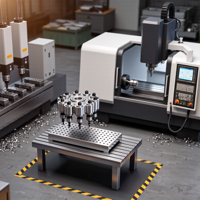
A multi-hole drilling machine uses two or more spindles to drill separate holes at the same time. The workpiece sits in a fixture, while spindle spacing matches the hole pattern. One press of the cycle control can produce several holes in a panel, bracket, or furniture component. That is the idea. Parallel drilling can shorten cycle time when hole locations repeat across many parts. It can also reduce repositioning, which helps keep holes aligned. But the fixture must hold the workpiece firmly; even slight movement can leave holes off-center.
The broader move toward factory automation is well documented. The International Federation of Robotics’ World Robotics 2024 report counted 4,281,585 industrial robots operating in factories worldwide in 2023, up 10 percent from 2022. That figure describes industrial robots, not multi-spindle drills, so it should not be treated as proof of drilling-machine performance. Still, it shows why manufacturers value repeatable, automated operations. In practice, spindle count is only part of the decision: hole spacing, material, tool wear, and chip removal all matter. A machine with more spindles is not automatically faster if setup takes longer or tools wear unevenly. The trade-off is easy to underestimate. A short production trial can reveal issues that a machine specification sheet cannot.
Fixed multi-spindle drills use a dedicated head with several spindles set at specific distances. Each spindle drills one hole, so a workpiece can receive a repeatable pattern in a single cycle. This suits parts made in batches, such as mounting plates with four corner holes or panels with evenly spaced fasteners. The head is configured for the job, not adjusted for every new layout.
Repeatability depends on more than spindle spacing. The part must sit firmly against its locating stops, and the fixture must resist vibration. Operators should check hole centers, tool condition, and chip clearance during setup. A worn drill or poorly seated plate can shift the result. Small errors add up.
The main limitation is flexibility. A fixed head may be fast for one pattern but inefficient when hole positions change often. Replacing or rebuilding the head can take time, and the workholding may need changes too. That trade-off is real. Before choosing this setup, compare expected batch size with the cost and time of dedicated tooling. A trial run on sample parts can reveal alignment or feed problems before full production begins.
Each spindle drills one hole at the same time, so a fixed head with more spindles can complete more holes per cycle. The configurations shown are illustrative examples, not industry-wide capacity figures.
Adjustable multi-spindle drills address a practical challenge: drilling several holes in one cycle when their spacing varies by part. Operators reposition spindles along the beam, matching the pitch to a drawing or fixture. This can reduce repeated setups and keep a row of holes aligned. Small details matter. Check the center-to-center distances, tool clearance, and clamp positions before production; a spindle may fit the layout but collide with a clamp.
The International Federation of Robotics’ World Robotics 2024 report records 541,302 industrial robots installed worldwide in 2023. That figure signals broader factory automation, not a guaranteed benefit from any particular drill. For a real job, run a sample panel and measure hole positions after clamping and machining. Also confirm that the adjustment mechanism locks firmly; pitch settings can drift if operators rush a changeover. One useful test is to drill a short batch, then compare the first and last parts. It is easy to overvalue spindle count. Flexibility only pays when adjustments are repeatable, and this is where a busy shop can still stumble.
CNC multi-spindle drills use programmable axes to position tools or workpieces for complex hole patterns. X and Y movements set locations, while Z controls drilling depth. Multiple spindles can drill several holes in one cycle, reducing repeated handling. One setup.
For example, a metal plate may need staggered holes with different spacing near its edges. The operator can program each position and adjust feed and depth for the material. Before full production, a test piece helps reveal errors in the pattern, tool alignment, or clamping. A coordinate on screen is not proof that a hole landed correctly.
Accuracy depends on more than programming. A rigid fixture keeps the workpiece from shifting, and suitable cutting tools help limit heat and burrs. Chips also need a clear path; packed chips can damage a hole’s finish or affect tool life. Complex patterns may require extra setup and careful checks, so more axes do not automatically mean faster production. Even a small offset can be costly across a full batch. Operators should inspect the first parts and revise the program when measurements disagree with the drawing.
| Machine Type | Spindle Arrangement | Typical Axis and Control Setup | Best Suited Hole Patterns | Key Advantages | Important Considerations |
|---|---|---|---|---|---|
| Fixed multi-spindle drill | Several spindles are mounted at fixed center-to-center spacing in a common head and generally drill at the same time. | Often uses a manually positioned worktable and a common feed motion; CNC may be used for part positioning on some models. | Repeated holes with consistent spacing on high-volume parts, such as plates, panels, and components with standard hole layouts. | Can reduce cycle time when many holes must be drilled simultaneously; consistent spindle spacing supports repeatable production. | Fixed spacing limits flexibility. A different pattern may require a different head, tooling arrangement, or setup. |
| Adjustable multi-spindle drill | Spindle positions can be set within the head’s adjustment range; the spindles commonly operate together. | Spindle spacing is usually adjusted during setup. The machine may have manual, powered, or programmable work positioning. | Multiple holes whose spacing changes between product runs but remains within the head’s adjustment range. | Offers more setup flexibility than a fixed head while retaining simultaneous drilling for suitable patterns. | Changing the layout can require manual adjustment and verification. Adjustment range and spindle count depend on the machine design. |
| CNC multi-spindle drill | Multiple spindles work in a coordinated head or spindle assembly; they are not necessarily independently positioned. | CNC-controlled axes typically position the workpiece, table, or drilling head along programmed directions. The number and configuration of axes vary by machine. | Repeated parts with multiple hole locations, including patterns that require programmed positioning between drilling operations. | Program storage and controlled positioning can improve repeatability and reduce manual indexing for recurring jobs. | Confirm which axes are CNC-controlled and whether the spindles drill together or in sequence; “CNC” does not automatically mean each spindle moves independently. |
| CNC drilling center with a single spindle | One spindle drills holes individually, repositioning between locations. | CNC-controlled positioning commonly moves the table, workpiece, or head across programmed axes; additional rotary axes may be available on some configurations. | Complex, varied, or frequently changing hole patterns, especially when hole locations or drilling sequences differ across parts. | Flexible programming supports complex layouts without requiring a multi-spindle head matched to every pattern. | Because holes are generally drilled one at a time, cycle time may be longer than simultaneous drilling when many identical holes are required. |
| Gang drilling machine | Multiple drilling units are arranged in a row, often allowing a workpiece to move from one station to the next. | Stations may use manual or powered feeds; CNC positioning depends on the specific machine configuration. | Parts requiring several operations in a defined sequence, such as drilling different hole groups at successive stations. | Several operations can be organized along one production line, reducing repeated handling between stations. | It is generally designed around a planned process sequence, so substantial changes to part geometry may require station or tooling reconfiguration. |
| Dedicated multi-head production drilling system | Two or more drilling heads are arranged to work on separate areas or faces of a part, depending on the system layout. | May combine fixed stations with programmable workpiece positioning; automation and axis control are configuration-dependent. | High-volume parts with multiple hole groups that benefit from drilling at different locations or orientations in one production setup. | Can reduce handling and support repeatable production when the machine is configured for a stable part family. | Requires careful matching of head layout, tool access, workholding, and part geometry; a dedicated setup may be less adaptable to unrelated jobs. |
Multi-hole drilling machines include gang drills, CNC multi-spindle units, and dedicated transfer systems. Their output depends on more than spindle count. Hole size and axis positioning need separate checks. ISO 286-1:2010 gives tolerance limits for hole dimensions; for a 20–30 mm basic size, an H7 hole has a 21 μm tolerance zone. That is a size limit, not a guarantee that every hole lands in the right place.
Check each machine axis against ISO 230-2:2014, which specifies tests for positioning accuracy and repeatability. A laser interferometer can record errors across the working stroke, including approaches from both directions. Run the test with the machine warmed up, and compare results with the job’s tolerance needs. Then drill a test plate. Real cutting adds tool runout, chip evacuation, and material variation. Small details matter.
A tidy axis report can still hide a poor hole pattern. For example, a machine may position well at the table center but drift near the far end of travel. That is easy to miss. I would compare axis-test results with measured hole diameters and center-to-center distances from the same setup. Standards guide the checks; they do not replace a representative cutting trial.
I&M Industrials Inc.
10 Akron Drive
Greenville SC 29605
Phone: 864-277-2450
GSA Number – GS07F0379Y